Andy Anthony, Managing Director of Monitran, explains how vibration and temperature condition monitoring are protecting a new biomass rail load-out system.
Biomass power stations have much in common with those that burn coal and oil, in that they can quickly generate power in order to meet fluctuations in demand. In many instances, coal- and oil-fired stations are being converted to process and burn biomass fuels. In other cases, new stations are being built.
For example, a new biomass power station is shortly to come online in the north of England. It will operate 24/7 and fuel will be transported to the station’s burners via a biomass rail load-out system which, in addition to rail carts, also includes hoppers, conveyors and feeders.
During the station’s construction, and keen to protect the biomass rail load-out system, the operator turned to sensors OEM Monitran and engineering reliability specialists Drive Management Services (DMS) to develop a conditioning monitoring system to interface with the site’s Supervisory Control and Data Acquisition (SCADA) system.
Scope of Work
In designing the condition monitoring system, Monitran and DMS determined that multiple assets should be monitored for rises in vibration and temperature levels; and that this could be achieved using 39 dual output sensors. The companies used their collective expertise to determine which parameters should be monitored. For example, fan and gearbox faults are best detected by measuring RMS velocity, whereas bearing wear is best detected by measuring acceleration.
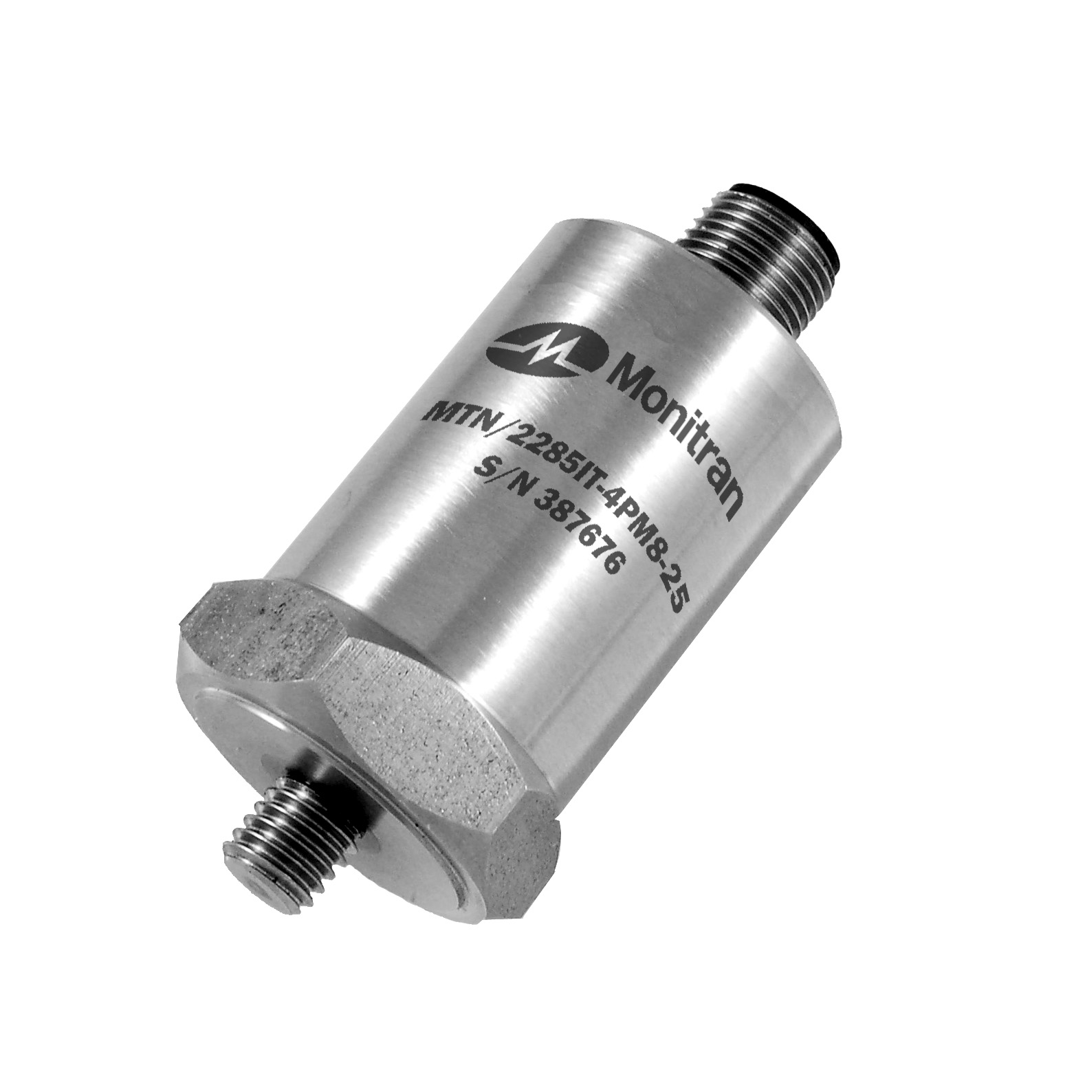
An important consideration was the environment, as biomass fuels represent a fire and explosion hazard and the main fuel handling area has been categorised as ATEX zone II. Accordingly, every aspect of the monitoring system in that area needs to be intrinsically safe. The sensor type selected for monitoring vibration and temperature levels was Monitran’s recently announced ATEX and IECEx Group II certified MTN/2285IT-4P (see figure 1).
The 39 dual output sensors are permanently mounted on key assets which include motors, gearboxes, fan assemblies and bearing housings. Regarding the sensitivity of the sensors, each was sized such that its outputs would be about 80% of maximum when mounted on their intended machinery. As for what the ’normal’ levels were likely to be, anticipated signal amplitudes were calculated from the design of the biomass rail load-out system and the datasheets of key equipment.
In most cases the sensors are wired into local junction boxes, typically one per asset. For example, one particular motor and gearbox assembly is protected by five sensors; two mounted orthogonally on the motor and three at strategic points on the gearbox. Screened multicore cables then connect the local junction boxes to a wall-mounted microprocessor-based condition monitoring unit, located in the site’s Motor Control Centre (MCC).
All wiring was carried out against a detailed asset-sensor-channel map produced for the project. Due to the size of the installation, some of the multicore cable runs are relatively long, up to about 200m, which also influenced the selection of devices with 4-20mA outputs as they are not so prone to signal losses over distance.
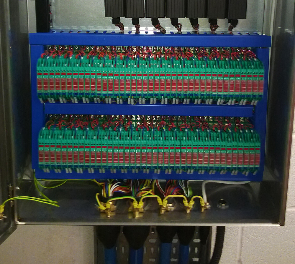
The condition monitoring unit was built and pre-calibrated by Monitran in High Wycombe and, whilst the MCC is not an ATEX II zone, consideration had to be given to the fact that the unit is electrically connected to sensors which are in a hazardous environment. Zener barriers were employed, (see figure 2) one per channel, to supress any voltages that could potentially cause a spark.
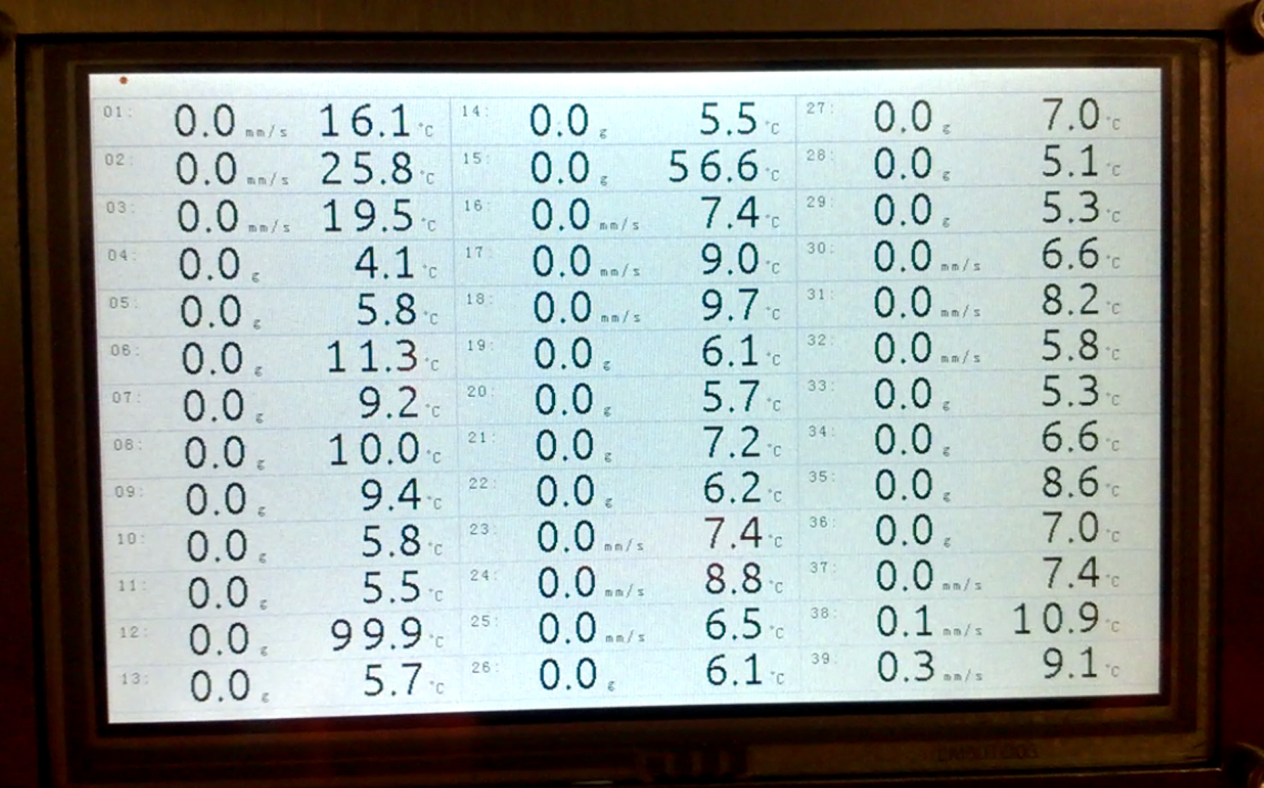
The unit has a 5-inch 800 x 480 pixel LCD screen, which is updated at five-second intervals and displays readings for the 78 channels (see figure 3), and connection to the site’s SCADA is via Modbus TCP Ethernet. The alarm level for each channel was set in the SCADA, on which a ‘look-back’ history can also be accessed to determine at what rate any of the conditions being monitored might be changing.
Following the installation of the condition monitoring unit, a commissioning phase began. Before the sensors were connected, the wiring was tested using appropriate voltages and currents; to replicate sensor outputs. This validated the integrity of the wiring and that it followed the asset-sensor-channel map. Once completed, the sensors were connected and as machinery came online it was reassuring to see that the sensors had been sized well. Next, realistic alarm levels were set in the SCADA; not too high, so that developing faults would go undetected for too long, and not too close to normal operating levels that false alarms might occur.
Conclusion
The design, development and installation of the biomass rail load-out system was a complex project due to the hazardous environment and having to work alongside numerous other contractors and engineers on site. The project was well executed, with the pre-calibration of the channels particularly paying dividend.
Also, whilst the system was a custom build, developed specifically for the biomass rail load-out application, the condition monitoring unit incorporates much of the technology Monitran developed in 2012 for monitoring the drivetrain of a hovercraft. That same technology is also at the heart of a recently launched commercial off-the-shelf condition monitoring system, the MTN/5000.
The biomass rail load-out condition monitoring system is doing its job, protecting the plant and equipment as the site comes online. In addition, the system will also be able to contribute data into a condition-based predictive maintenance schedule.

Figure 1. Certified to ATEX and IECEx Group II, the MTN/2285IT-4P is an intrinsically safe dual output sensor with a 4-20mA DC current output proportional to velocity (mm/s) or acceleration (mm/s/s) and a DC voltage proportional to temperature.

Figure 2. Above, 78 Zener barriers (the green and red components) provide intrinsic isolation between the condition monitoring circuitry and the sensors connected to equipment in the ATEX II zone.

Figure 3. Above, the condition monitoring unit’s display (photo taken during commissioning) shows all 78 channels for the 39 dual output sensors.